Cabinet Sensor
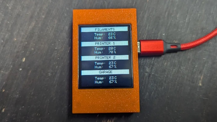
Display temperature and humidity from up to 4 sources. They connects wirelessly with no WiFi required. Used to keep track of fermenter cabinets, fridges, kegerator, rooms, etc...
Bill of Materials
3D models
Code
- ESP32 code
Tutorial
Programing the ESP32 S2 Mini
If you need help setting up the environment for programming an ESP32, please refer to this tutorial
You will need to program the ESP32. It will be much easyer to program it before your begin. Download the arduino IDE projects from GitHub then upload it to the ESP32. Make sure you select "LOLIN S2 Mini" from the board list and upload the display firmware to 1 ESP32 and the sensor firware to the others. Keep track of which on is which!
Here are some modifications you might want to do the the firmwares before uploading them:
Display firmware:
- Modify the probeCount variable to the amount of probes you plan to use.- Change the probeName1, probeName2, probeName3 and probeName4 variables to how you want them named on the display. I suggest names length of 10 characters maximum.
- If you plan to use more than 4 probes, you will need to set up more displays and modify the displayName variable to something unique for each one.
Probe firmware:
- Change the probeName variable. Those names must fit the names you set in the display firmware.- Again, if you plan to use more than 4 probes, you will need to modify the displayName variable to the name of the display that this probe reports to.
Display
First, print or order the display case.
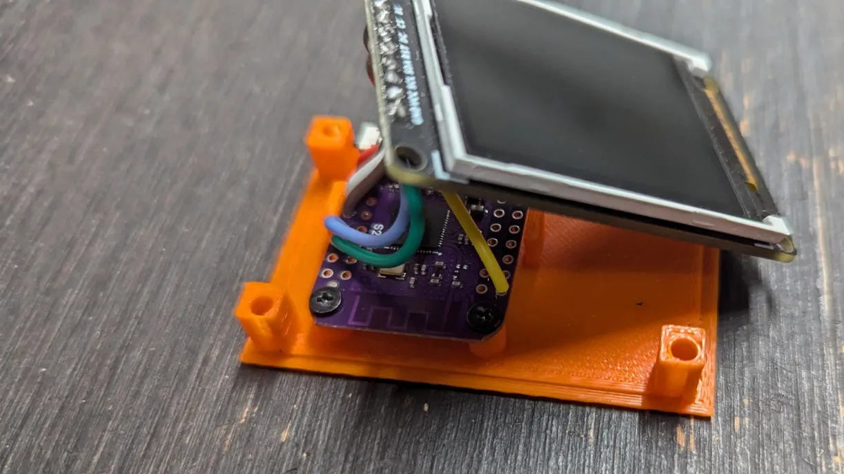
Then solder the required wires to the display. I suggest using the same colors I did to prevent mistakes.
Now solders the wires to the right pins on the ESP32. Make sure it is the one with the display firmware on it.
Secure the ESP32 to the enclosure with m2 screws. I got mine in an old laptop.
Install the top part of the enclosure This should be a friction fit. If not, use 4x M3x16 screw to secure the cover in place.
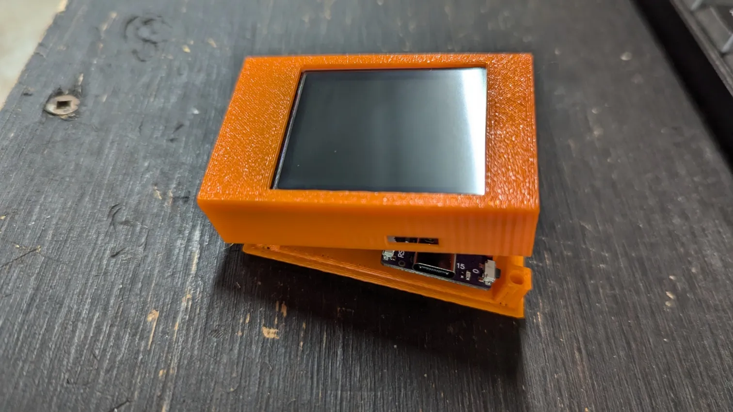
The screen is done!
Sensor
Again, print or order the sensor enclosure.
Then solder the required wires to the probe. I again suggest using the same colors I did to prevent mistakes.
Now solders the wires to the right pins on the ESP32. Make sure it is one with the probe firmware on it.
Fit the ESP32 and the probe in their respective location in the enclosure.
Place the enclosure lid and you are done! Note that depending on your printer tolerences you might have to glue the lid.
You are done! Plug in everything and enjoy a nice cold beer. You deserve it. Cheers!